
English 
T: +86-21-55896873
E: info@youguard.cn
E: info@youguard.cn
8th Floor, Building 3, 999 Jiangyue Road, Minhang District, Shanghai
Views: 0 Author: Site Editor Publish Time: 2026-11-09 Origin: Site


Installing a protective cover on an industrial robot solves environmental contamination issues but introduces new mechanical variables. Notably, you must manage movement restriction and spatial conflict. Protective fabrics often clash against rigid automated systems. When materials bunch or stretch, they fight the machine's intended trajectory.
Without rigorous validation, poorly fitted covers can trigger over-torque errors, restrict maximum reach, or cause premature material failure. These mechanical faults often lead to the exact manufacturing downtime the protective suit was meant to prevent. Engineers must address these friction risks before full deployment. Ignoring clearance tolerances creates immediate hazards on the production floor.
To ensure seamless automation, facilities must establish a standardized approach to validating spatial tolerances. This guide outlines the necessary testing protocols, evaluation criteria, and implementation steps. You will learn how to verify protective fabric performance prior to full-scale deployment. Implementing these steps guarantees your automation remains fast, safe, and entirely unhindered.
Comprehensive motion testing ensures protective covers do not compromise the robot’s kinematic range, payload capacity, or cycle times.
Validating robot cover joint clearance at maximum articulation points is critical to preventing material snags and motor strain.
Long-term reliability requires dedicated robot cover fatigue testing to identify thermal retention and structural wear under continuous operation.
Pilot testing and iterative vendor prototyping mitigate the financial risks of fleet-wide cover deployment.
Deploying unverified protective suits on a busy production floor introduces hidden operational penalties. Many facilities install custom fabrics to shield automated arms from weld spatter, corrosive chemicals, or abrasive dust. However, bypassing clearance validation transforms a protective asset into a mechanical liability. You must evaluate how the added bulk affects daily operations.
Mechanical strain presents the most immediate risk. When a suit fits too tightly around a robotic joint, outward articulation creates severe fabric tension. The robot’s servo motors must work harder to overcome this physical resistance. This added effort triggers servo over-torque faults, forcing the system into an emergency stop. Furthermore, continuous resistance demands higher current draw, escalating overall energy consumption across your robotic fleet.
Material degradation quickly follows mechanical strain. Frequent material replacements severely impact maintenance budgets. When suits lack proper spatial clearance, the fabric pinches between metal castings during inward rotational movements. The exterior surface also suffers abrasion when it repeatedly rubs against end-of-arm tooling (EOAT) or nearby safety fencing. This constant friction causes micro-tears, destroying the protective barrier.
To avoid these operational pitfalls, teams must define strict success criteria before launching a validation phase. A successful testing period should demonstrate the following outcomes:
Zero safety stops: The system must execute its entire programmed trajectory without triggering collision alarms or over-torque faults.
Optimal thermal equilibrium: Internal motor temperatures must remain well within the original equipment manufacturer (OEM) safety margins.
Unimpeded cycle speeds: The fabric must not create drag, allowing the robotic cell to maintain its baseline production speed.
Zero material snagging: Visual inspections must confirm the fabric never catches on pneumatic lines, cables, or joint crevices.
Before installing any protective material, engineers must capture a comprehensive performance baseline. You cannot accurately measure the impact of a suit without knowing how the bare robot behaves. Standardized robot cover motion testing requires a controlled dataset to highlight discrepancies later in the process.
First, review the operational parameters established by the OEM. Every industrial arm possesses strict kinematic limitations and payload specifications. Consult the technical manual to understand the spatial boundaries of your specific robotic cell. You need to identify how close the bare arm currently comes to external infrastructure, fencing, and tooling racks. If clearance is already tight, adding a thick Kevlar or Teflon suit will require careful path adjustments.
Facilities rarely push robots to their absolute theoretical limits, but validation demands extreme testing. You must identify the extreme limits of the required trajectory for your specific application. Program a specialized diagnostic routine incorporating these extreme movements:
Maximum outward extension: Drive the arm to its furthest reach to test ultimate fabric stretch and tension limits.
Tightest rotational curl: Fold the arm completely inward to identify where bulk material bunches up and creates pinch hazards.
High-speed wrist rotation: Spin Axis 6 rapidly to observe how the fabric behaves around the EOAT under centrifugal force.
Modern robotic controllers act as highly sensitive diagnostic tools. Utilize your controller interface to monitor baseline motor loads before applying the suit. Record the peak torque values, average current draw, and baseline operating temperatures for every single axis during the worst-case posture routine.
Save this control dataset. Once you dress the automated arm, you will run the exact same routine and compare the new data against these baseline figures. A minor increase in current draw is acceptable due to the added weight of the fabric. However, sharp spikes indicate severe fabric binding.
Best Practice: Always conduct baseline tests at the actual production speed. Running a baseline at 10% speed will not accurately reflect the dynamic friction and centrifugal forces experienced during normal operations.
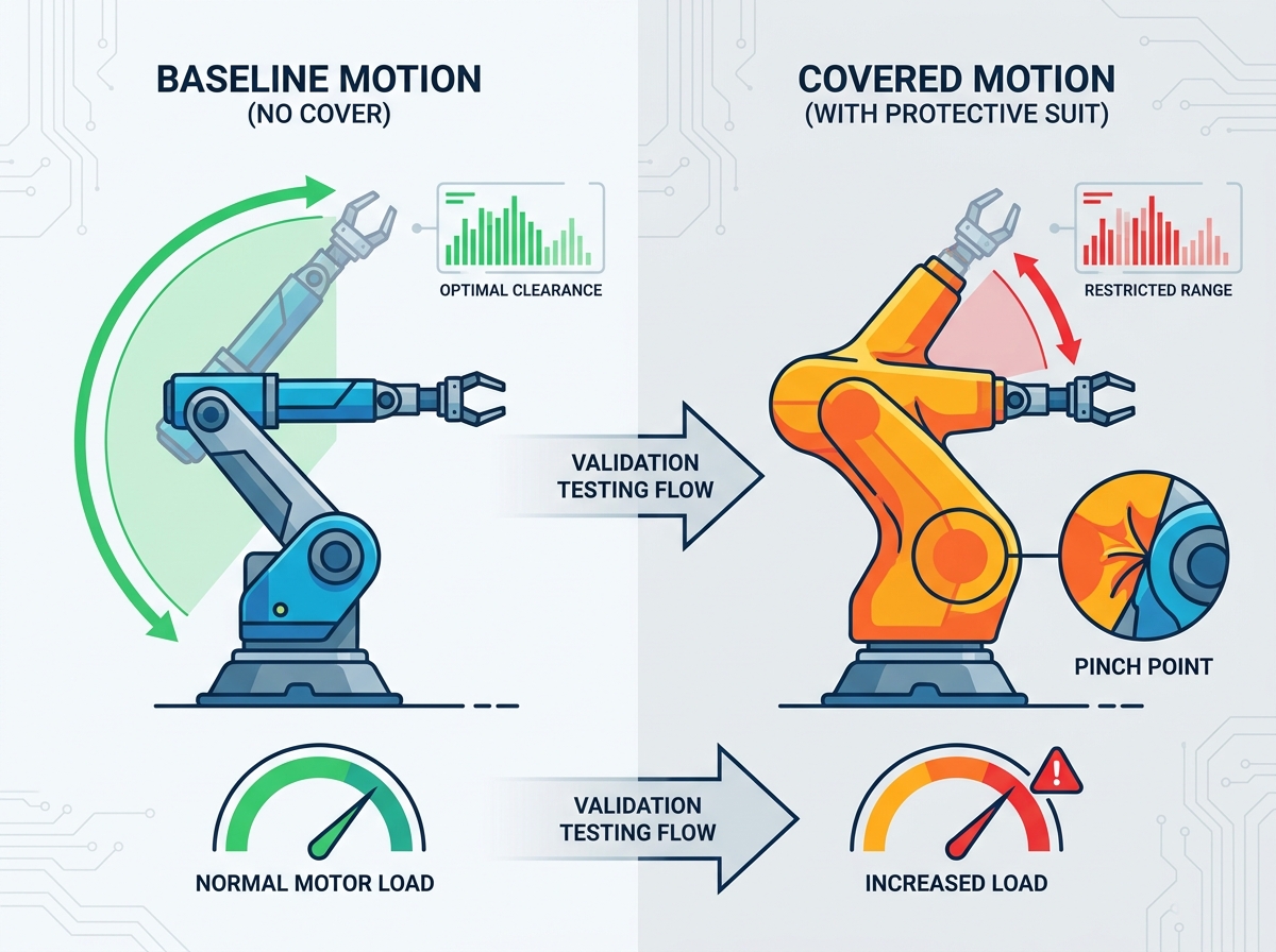
Once you secure the suit onto the machinery, the physical validation phase begins. Validating robot cover joint clearance prevents unexpected snags and protects vital internal components. This process requires a slow, deliberate approach before ramping up to full production speeds.
Begin by isolating movements across Axes 1 through 6. Move one axis at a time while keeping the others stationary. This isolation allows observers to watch material behavior at individual articulation points. If you move all axes simultaneously, identifying the exact source of a fabric bind becomes nearly impossible.
During this slow articulation, pay close attention to integrated cable management. Protective suits often share space with internal pneumatic lines, sensor cables, and heavy umbilicals. The fabric must glide smoothly over these components. If the suit grips a cable during a sweeping motion, it could rip the connector directly out of the controller.
Inward articulation creates bunching. As the arm folds, excess fabric has to go somewhere. Conduct thorough visual and tactile inspections to locate where material gathers. If the fabric bulges into a joint crevice, the metal castings will chew through the material during the next cycle.
Conversely, outward articulation tests the tension limits. Measure fabric tension during maximum extension. The material should remain slightly slack even at full reach. If the fabric becomes drum-tight, it acts as a mechanical limiter, fighting the servo motors and drastically reducing the lifespan of the suit’s seams.
Table 1: Axis Articulation Inspection Matrix
Axis Number | Primary Movement Type | Common Clearance Hazards | Inspection Focus |
|---|---|---|---|
Axis 1 | Base Rotation | Friction against base mounting plates. | Ensure bottom hem does not drag on the floor. |
Axis 2 & 3 | Lower/Upper Arm Pitch | Severe material bunching in the elbow joint. | Check for fabric pinching between castings. |
Axis 4 | Arm Roll | Fabric twisting and constricting internal cables. | Verify material allows full 360-degree rotation. |
Axis 5 & 6 | Wrist Pitch and Yaw | Interference with end-of-arm tooling (EOAT). | Confirm cuffs do not block sensor lines or nozzles. |
Protective fabrics add physical volume to the automated arm. A heavy-duty insulated suit might add two inches of girth around the entire machine. You must ensure this added volume does not violate safety zones. Drive the robot through its standard routine and watch its proximity to cell fencing, part bins, and tooling racks. A collision that previously missed a rack by half an inch will now cause a destructive impact.
Short-term clearance checks confirm basic fitment, but they cannot predict how materials degrade over thousands of operating hours. Long-term reliability requires dedicated robot cover fatigue testing. This phase highlights thermal retention issues and structural wear under continuous, punishing operation.
You cannot afford to wait six months to see if a suit fails. Instead, set up an accelerated wear simulation. Program the robotic cell to run continuous, high-speed cycle loops during a weekend or scheduled maintenance shift. This process simulates weeks of production stress within a condensed timeframe. Force the machine to repeat its most aggressive, high-articulation movements thousands of times.
Common Mistake: Running a fatigue simulation without the actual production tooling attached. The EOAT adds weight and alters the center of gravity, significantly changing how the fabric stretches and pulls during high-speed swings.
Heavy protective materials act like winter coats. They trap heat generated by the servo motors and gearboxes. Measuring heat retention under the protective material forms a critical part of fatigue analysis. Use thermal imaging cameras or integrated temperature sensors to monitor the system during the accelerated simulation.
You must ensure servo temperatures remain strictly within OEM safety margins. If temperatures climb too high, the controller will initiate thermal throttling, slowing down the arm to prevent hardware damage. This throttling directly destroys your production cycle times. If the suit retains excessive heat, you may need to request forced-air ventilation ports or breathable fabric panels from your vendor.
Once the simulation concludes, shut down the cell and perform a meticulous physical inspection. Look closely at the seams, zippers, and hook-and-loop closures. Sustained mechanical stress often causes micro-tears near the joint bends. Check the adhesion strength of the Velcro strips; high-speed centrifugal force can easily rip poorly secured closures open, exposing the sensitive machinery beneath.
Gathering testing data provides no value unless you actively use it to refine your deployment strategy. After completing the physical evaluations and fatigue simulations, engineering teams must sit down and analyze the results. This data-driven approach prevents catastrophic failures during live production runs.
Pull the logs from your controller. Compare the post-cover motor torque and temperature data directly against your pre-installation baseline metrics. Look for hidden friction. If Axis 3 shows a 15% increase in current draw, you know the fabric is binding around the elbow joint, even if it looks fine to the naked eye. Objective data always supersedes subjective visual inspections.
When tests reveal clearance failures or thermal issues, you face a critical decision. You must choose between modifying the robotic trajectories to accommodate the bulky fabric or requesting engineering revisions from the cover manufacturer.
Adjusting the programmed path offers a fast solution. Smoothing out a harsh corner or reducing a maximum extension point might instantly solve a tension problem. However, modifying paths can increase cycle times. If cycle times must remain untouched, you must send your diagnostic data back to the vendor and request a tailored redesign.
Never deploy a newly designed suit across an entire factory floor simultaneously. Embrace a phased rollout strategy. Isolate the tailored fabric to a single pilot cell for a 30-day production trial. Monitor this pilot cell relentlessly. This isolation ensures that if an unforeseen fatigue issue destroys the material in week three, you only face downtime on one machine rather than fifty.
The success of your clearance validation heavily depends on the manufacturer supplying the protective gear. Not all vendors provide the same level of engineering support. Evaluating partners properly ensures you receive a product capable of passing strict diagnostic criteria.
Assess vendors based on their willingness to provide custom tailoring. An off-the-shelf suit rarely fits perfectly. Look for manufacturers who embrace iterative prototypes based on your specific motion test data. If your tests reveal a pinch point on Axis 2, a strong vendor will rapidly supply a revised prototype with added gussets or flexible expansion joints to solve the exact issue you documented.
Refuse to work with vendors who cannot verify their fabric properties. Require manufacturers to provide comprehensive technical data sheets (TDS) for every material layer. You need documented proof regarding fabric tensile strength, chemical resistance, and thermal conductivity. If a vendor claims a material breathes well, the TDS must prove it allows sufficient airflow to prevent servo overheating.
Finally, evaluate the long-term partnership criteria. Review the warranty terms carefully. Understand the replacement part availability for high-wear components like wrist cuffs or base skirts. Secure Service Level Agreement (SLA) guarantees for future design modifications. Manufacturing processes evolve, and your protective suits will need to adapt alongside new tooling and changing production demands.
Validating spatial clearance and motion capabilities transforms a simple protective cover from a potential operational liability into a highly reliable asset. Implementing a strict evaluation process ensures your automated systems remain protected against environmental hazards without sacrificing their intended speed, reach, or efficiency.
We strongly recommend prioritizing objective testing data over theoretical fitments. Never assume a suit fits just because it zips up easily. Always run comparative diagnostics on motor load, tension limits, and internal temperature fluctuations to guarantee long-term operational health.
Your next step is to engage a custom manufacturing partner for a comprehensive site evaluation. Provide them with your unique robotic cell parameters and request an initial prototype designed specifically for your required trajectories and tooling configurations.
A: Initial dry-run clearance checks take only a few hours. Engineers move the arm slowly through its axes to find immediate pinch points. However, continuous fatigue testing requires several days to weeks. This extended period proves the material can survive repetitive friction and highlights gradual thermal retention issues.
A: Slight increases in motor load (typically 2-5%) are perfectly normal due to the added weight and natural aerodynamic drag of the fabric. However, sharp load spikes approaching OEM fault thresholds indicate an improperly fitted suit creating dangerous mechanical resistance against the servos.
A: Do not rely solely on the currently active program. Instead, map and test the absolute maximum reach and the tightest rotational constraints physically possible within the cell. Validating these worst-case extremes ensures the material will perform safely regardless of future programming changes.
A: Short clearance tests lasting a few minutes cannot predict thermal problems. Heat builds up gradually. To accurately identify thermal retention risks, you must conduct sustained fatigue testing over several hours while utilizing thermal imaging cameras to monitor casing temperatures beneath the fabric.


