
English 
T: +86-21-55896873
E: info@youguard.cn
E: info@youguard.cn
8th Floor, Building 3, 999 Jiangyue Road, Minhang District, Shanghai
Views: 0 Author: Site Editor Publish Time: 2026-08-21 Origin: Site


Unplanned downtime ruins production schedules and destroys profit margins. Worn, snagged, and degraded cables on active robotic cells cause massive headaches for facility managers. When automated lines stop abruptly, you lose time and money immediately.
Retrofitting existing setups presents a serious operational dilemma. Disconnecting complex cable harnesses to install traditional closed-tube management systems forces unacceptable production stops. Re-pinning cables and recalibrating sensors takes hours you simply cannot spare. Maintenance teams need a better way to protect these vital assets without halting the entire factory floor.
You need a practical method to protect live automated systems. A split robot arm cable cover provides the ideal retrofit solution. We will explore how you can evaluate, specify, and install these protective sleeves. You will learn to execute this upgrade without compromising OEM warranties or altering complex robot kinematics.
Zero-Disconnect Retrofitting: Split covers allow installation directly over existing harnesses, bypassing the need for tedious cable de-pinning or recalibration.
Payload and Kinematic Preservation: Evaluating the weight limits and bend radius of split covers prevents undue stress on servo motors and joint axes.
Risk Mitigation: Proper anchor placement and tension testing are critical to prevent the split seam from separating during high-speed, multi-axis movements.
Sourcing Strategy: Utilizing an OEM robot protection service ensures material compliance (e.g., heat, chemical, or weld-spatter resistance) tailored to specific operating environments.
You must constantly monitor the health of your automated cells. We rely on clear indicators to determine when an existing harness requires immediate intervention. Look closely at your equipment during routine inspections. Visible jacket abrasion often serves as the first warning sign. When outer insulation wears thin, internal copper conductors face imminent exposure. You might also notice frequent localized faults. These micro-interruptions happen when damaged cables bend in specific orientations. Interference with tooling during automated tool changes presents another critical red flag. Do not ignore these symptoms.
Consider the stark financial differences between taking action now versus delaying maintenance. We must evaluate the cost of installing a split retrofit against a complete system overhaul. Replacing an entire OEM cable harness demands a massive capital outlay. Worse, you incur severe MTTR (Mean Time to Repair) penalties. Tearing down a robotic cell to route new continuous cables keeps your production line idle for shifts at a time. A split cover costs a fraction of full replacement. It deploys quickly and keeps the line moving.
We define successful retrofits through strict operational criteria. First, you must maintain current cycle times. The added protection cannot slow down your robot. Second, you must achieve zero disconnection during installation. Live-wire installation defines the value of this upgrade. Finally, you need to extend the harness lifespan by a measurable baseline. Tracking cycle count improvements proves the investment works. You want cables to last millions of cycles longer.
Engineers face a continuous debate between solid dress packs and split management systems. We must understand the inherent advantages and limitations of both approaches to make an informed choice.
Solid or continuous dress packs dominate certain extreme environments. They offer maximum ingress protection. You can achieve high IP ratings, keeping out microscopic dust and pressurized fluids. They also provide high structural rigidity. However, they carry severe operational drawbacks. You must perform complete cable disconnections to install them. This guarantees high installation downtime. Furthermore, maintenance crews find it incredibly difficult to inspect internal cable health once sealed.
Split management systems prioritize agility. They feature a unique sidewall entry system. Whether using an industrial zipper, high-strength Velcro, or an interlocking seam, they allow live-wire installation. You simply wrap them around the existing bundle. They also grant extremely easy maintenance access. When you need to inspect a wire, you just open the seam. However, they possess a lower inherent IP rating against submerged fluids. Water can penetrate the seam under pressure. They also require careful seam orientation. You must position the closure to avoid snagging on the robot's casting during complex movements.
Decision Matrix for Cable Management Selection
Feature / Requirement | Solid Dress Pack | Split Cover System |
|---|---|---|
Installation Downtime | High (Hours to Days) | Low (Minutes) |
Ingress Protection | Excellent (IP67+) | Moderate (Dust/Splash) |
Maintenance Access | Difficult | Simple & Fast |
Abrasion Resistance | High | High (Material Dependent) |
Retrofit Capability | Poor | Excellent |
Use this matrix to guide your design choices. You should compromise on absolute sealing only when installation speed and mechanical abrasion protection hold higher operational value.
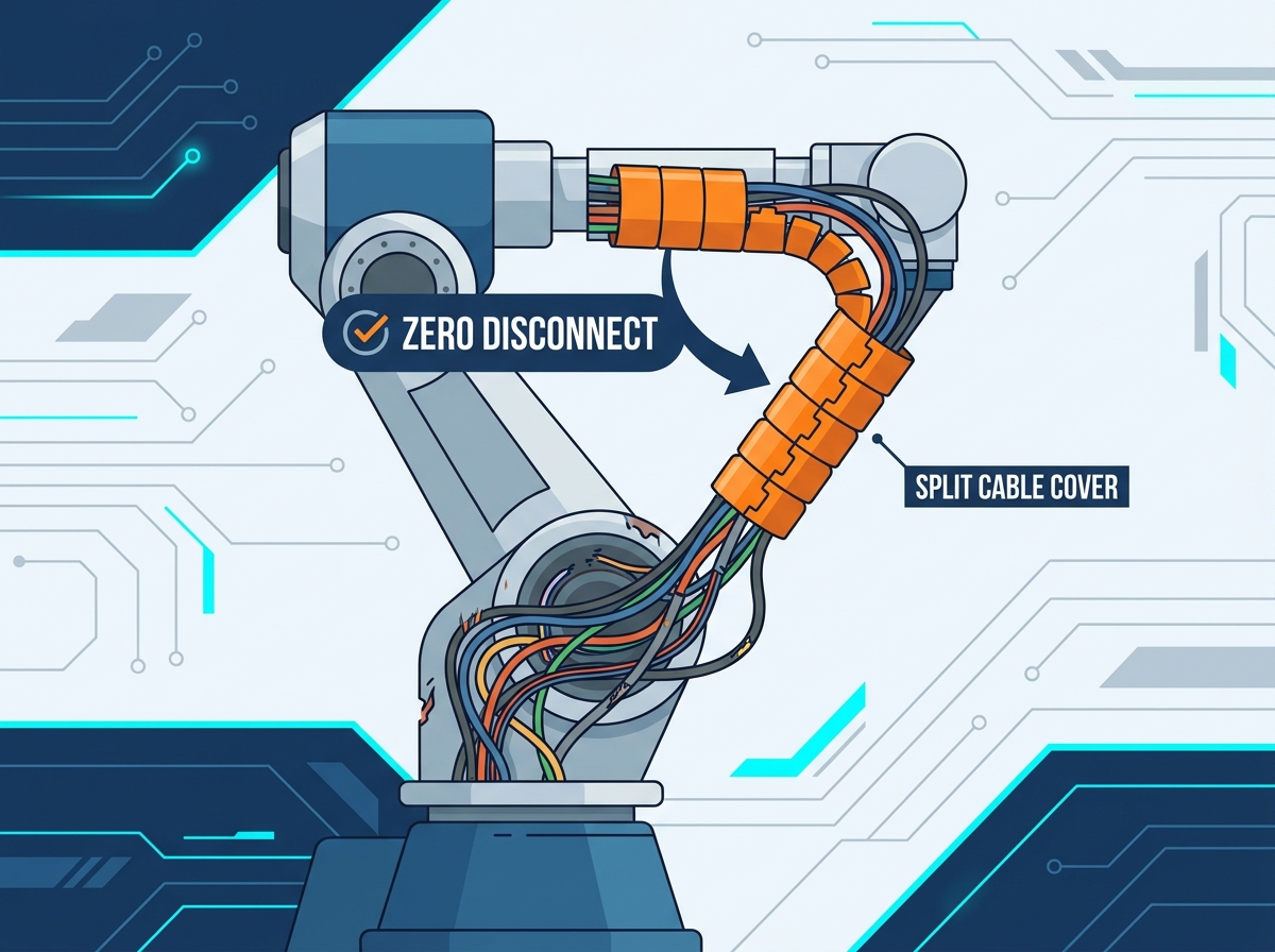
Adding any component to an industrial arm alters its physical operating profile. You must evaluate weight constraints and payload capacity thoroughly. Added mass from the cover and mounting brackets directly impacts the robot’s dynamic payload. We see this effect most prominently on Axes 4, 5, and 6. Heavy attachments increase inertia. This forces servo motors to work harder, accelerating wear. Implement lightweighting strategies early. Select specific polymer blends or engineered fabrics. Thin-wall polyurethane or woven textiles offer protection without unnecessary bulk.
Kinematic impact requires precise mathematical consideration. You must calculate the minimum bend radius of the newly combined harness and cover. If the protective sleeve resists bending too much, it forces cables to kink. We must absolutely prevent "corkscrewing" inside the split sleeve. Torsion fatigue happens when cables twist repeatedly in one direction without relief. Copper strands harden and snap. Ensure the internal volume of the sleeve allows cables to glide freely during multi-axis articulation.
Environmental compatibility dictates your material selection. Factory floors present diverse chemical and thermal hazards. We match cover materials directly to these operating realities. Use Kevlar-blended materials for foundry environments and heavy welding cells. It resists extreme heat and weld spatter. Select PTFE (Teflon) covers for food processing or chemical washdown zones. PTFE repels harsh cleaning agents. Choose standard heavy-duty polyurethane for general manufacturing tasks requiring high mechanical abrasion resistance.
Proper installation ensures the cover functions without hindering robot mobility. We follow a strict four-phase framework to guarantee success on live systems.
Phase 1: Pre-Installation Audit
Never apply a cover blindly. Begin by mapping the robot's full range of motion. Jog the arm manually through its most extreme program points. Identify all pinch points where the casting closes in on itself. Determine exactly where you need slack loops. These service loops provide the necessary length for the arm to reach full extension without yanking the base cables.
Phase 2: Anchoring and Routing
Routing dictates the lifespan of the bundle. Select non-destructive mounting points carefully. Use engineered strain relief brackets. Rely on rotary brackets specifically designed for Axis 3 and Axis 6. These brackets allow the bundle to pivot naturally. Rigid zip-tying directly to the casting causes premature failure. A tight zip tie acts like a guillotine. It concentrates stress at a single point, cutting through the jacket over thousands of cycles.
Phase 3: Applying the Split Cover
Enclose the cables gently. Use techniques that avoid inducing localized pinch points. Smooth the cables out so they lie flat against one another. When closing the zipper or pressing the Velcro, check for trapped wires. You must orient the split seam strategically. Always face the closure away from known friction zones. Point it outward, away from robotic joints and metal edges.
Phase 4: Validation and Testing
Testing proves your installation geometry. Start by running the specific robot program at 10% speed. Watch closely. Increase to 50% speed, then finally to 100% production speed. Observe the cover for any signs of snagging. Look for over-tension during wide swings. Ensure the seam shows no signs of separation under rapid acceleration.
Many facilities attempt a DIY approach first. We frequently see maintenance teams buy generic split tubing from standard electrical suppliers. Discussing the limitations of off-the-shelf solutions helps you avoid expensive mistakes. Applying generic hardware-store tubing to complex 6-axis cobots or heavy-duty industrial arms introduces massive risks. Generic plastics exhibit unpredictable wear patterns. They often become brittle and shatter. Furthermore, clamping unapproved aftermarket accessories onto sensitive joints can void expensive manufacturer warranties.
Professional sourcing eliminates these risks. An OEM robot protection service provides immense value. They deliver custom-tailored lengths precisely cut for your application. They provide pre-engineered mounting kits matched perfectly to specific robot models. Whether you run a FANUC, a Universal Robot (UR), or a massive KUKA, they have a tested bracket geometry. Professional vendors also supply crucial compliance documentation. You receive UL ratings for fire safety. They provide cleanroom ISO certifications for semiconductor labs. They supply ATEX ratings for explosive environments.
Lead Times: Ask how quickly they can manufacture and ship custom lengths. Minimize your exposure time.
Material Testing Data: Request laboratory proof of abrasion resistance and chemical compatibility.
Historical Cycle-Life Benchmarks: Ask for case studies showing how many millions of cycles their product withstands in similar industrial applications.
Bracket Compatibility: Verify they offer non-destructive clamps that fit your exact robot casting without drilling.
Protecting live automated lines requires smart interventions. A split robot arm cable cover stands as a high-ROI, low-downtime solution. It shields existing harnesses from catastrophic failure without forcing you to halt production for days. You must simply respect the mechanical limits. Monitor added weight, preserve kinematic freedom, and secure anchors correctly.
Take proactive steps today to secure your automation investments. Encourage your engineers and facility managers to audit their current robotic cells immediately. Look for those early warning signs of cable wear. Do not wait for a complete wire fracture. Consult with a specialized protection service to map out a targeted pilot installation on your most vulnerable machine.
A: No. While highly resistant to dust and splash, the seam inherently prevents an IP67/IP68 rating. They are designed for abrasion, impact, and spatter protection, not submersion.
A: Measure the bundle's thickest point, calculate the cross-sectional area, and ensure the cover's internal volume allows for 15-20% free space to allow cables to glide internally during bending.
A: It can if the added bulk interferes with the cobot's built-in force-torque sensors or creates new pinch points. It requires recalibrating the payload settings and evaluating the new outer profile.
A: Visual inspections should be integrated into standard monthly PM (Preventative Maintenance) schedules, looking specifically for bracket slippage or seam fraying.


